this post was submitted on 16 Jun 2023
1 points (100.0% liked)

Soldering

471 readers
2 users here now

This community is for electronic hobbyists to discuss projects and is focused on soldering. Everyone is welcome from the noob to people who have been soldering as a hobby for decades to people who solder professionally. We'll talk about materials and techniques, equipment, and projects. Everyone is welcome. All questions are welcome. Post photos and ask for help.

RULES:

  1. All Lemmy.ca rules apply here.

  2. Everyone (see rule 98) is welcome.

  3. If you’ve seen a question 100 times answer it the 101st time or ignore it. Even better, write a complete, detailed answer and suggest that the mod(s) pin it to the community.

[Did you actually think there were 98 rules?]

  1. If you present something as fact and are asked to provide proof or a source provide proof or a source. Proof must be from a reliable source. If you fail to provide proof or a source your post or comment may be removed.

  2. Don’t be a dick. Yes, this is a catch-all rule.

  3. The mod(s) have the final say.

founded 1 year ago
MODERATORS
 

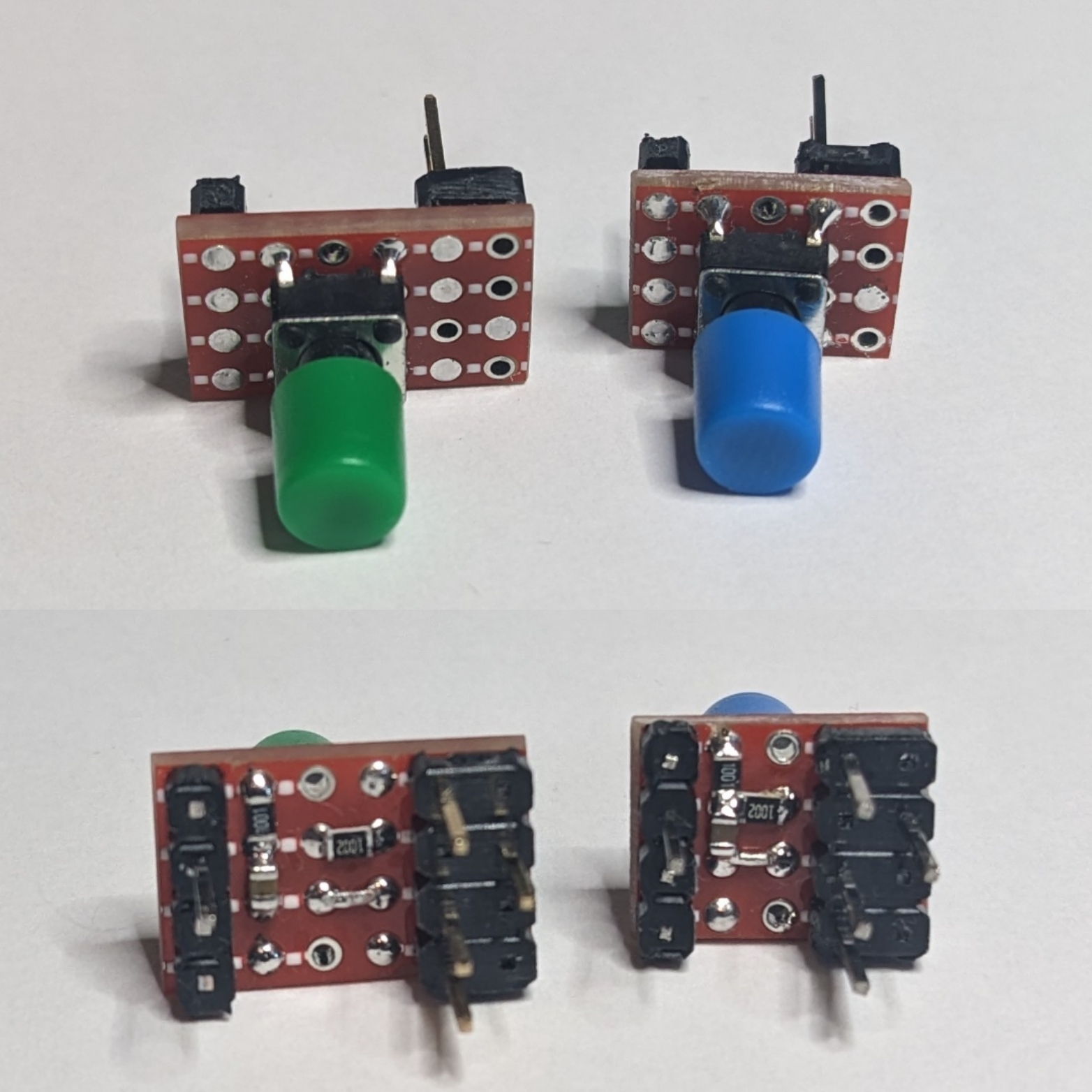
This is a cool little project. I often prototype circuits on solderless breadboards. I've mostly switched to using 0805 SMD resistors and capacitors. I have a box of 1/4W 1% and a box of 1/2W 1% THT resistors but they aren't neat when they're plugged into the breadboard. I've got 0.1uF capacitors but no 1.0uF in THT.

I decided to make up these little tact switches ready to plug into the breadboard with built in hardware debounce. The debounce circuit also provides a pull-up resistor.

Each switch has a 10K 0805 resistor between Vcc and the MCU pin, a 1.0uF 0805 capacitor between GND and the MCU pin, and a 1K resistor between the switch and the MCU pin. The end result is a nicely debounced going low switch with a built in pull-up. They work great and I can just grab one when I need one and plug it in. I've made versions that will plug into one side or the other of the breadboard so that I can have a switch on either side depending on what works best.

The row with 3 pins is GND and the adjacent row with 1 pin is Vcc. The single pin at the other end is the debounced switched output to the MCU pin.

If anyone's interested I can post pictures of the process of making these and how I wire them up so that the work correctly.

no comments (yet)
sorted by: hot top controversial new old
there doesn't seem to be anything here